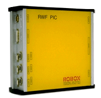
The main features are:
- PIC17C42 microcontroller
- 24VDC power supply
- It receives signals from the two guide antenna coils, filters them with a narrowband filter at 10 KHz, demodulates and sends them, and outputs two control voltages (ranging from 0 to 10V), to the Robox control unit for the guide purposes.
- It receives signals from the center, through two guide coils, directed to the vehicle. It decodes the Manchester Code and sends it in asynchronous via RS232 (9600 baud) to the Robox control unit.
- It receives communications from the Robox control unit asynchronously via RS232 (9600 baud), directed to the centre, encodes Manchester on a 17 KHz carrier and transmits them, via a dedicated antenna, onto the guide wire.
- It receives two signals from the Hall-effect transducers of the magnetic antennas for position detection along the wire. It converts them into two voltages of -10/+10V and sends them to the Robox control unit, which will use them for centering on the stop stations.
- It receives the signals from the two centering antenna coils (similar to the guide coils), filters them with a narrowband, demodulates and sends them as two voltages ranging from -10 and +10V, to the Robox control unit, which will use them for centering on the stop stations.
- It receives the measured signals of battery voltage and current from the Hall-effect transducers and sends them to the Robox control unit for optimization of charging strategies.
- Please note: RWF can receive and process signals from up to 3 inductive antennas (2 simultaneously) and 2 magnetic antennas.


